Place of Origin: | USA |
Brand Name: | Honeywell |
Certification: | COC |
Model Number: | 621-1151 |
Minimum Order Quantity: | 1 Piece |
---|---|
Price: | inquiry |
Packaging Details: | original |
Delivery Time: | 3-5 work days |
Payment Terms: | T/T |
Supply Ability: | 10 Piece per a day |
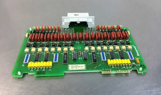
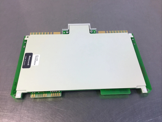
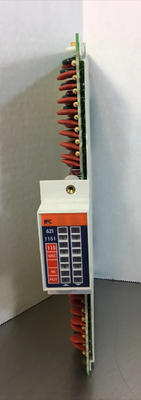
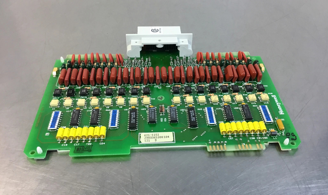
Product Name: | Honeywell 621-1151 Analog Input Board 115V AC, 16-pt. PLC Module | Product Model: | 621-1151 |
---|---|---|---|
Condition: | New | Shipping: | DHL,TNT Or EMS,Fedex,UPS |
Stock: | Available | Warranty: | 12 Months |
Rating: | 24Vdc, 110mA | Packing Size: | 11.8" X 7.9" X 9.9" (30 Cm X 20 Cm X 25 Cm) |
Gross Weight: | 3kg | ||
Highlight: | Honeywell 621-1151 Analog Input Board,Honeywell 16-pt. Analog Input Board,Honeywell 115V AC Analog Input Board |
Honeywell 621-1151 Analog Input Board 115V AC, 16-pt. PLC Module
Product Details:
Brand Name | Honeywell |
Model | 621-1151 |
Catalog | TDC2000 |
Origin | United States (USA) |
Dimension | 30*25*20cm |
Weight | 3kg |
HS Code | 8537101190 |
Payment | T/T |
Sales Price | $100 |
Warranty | 12 months |
Lead time | 3-5 work days |
Additional Information:
BATTERY C SIZE LITHIUM | 7001_Modular Controllers |
PARALLEL I/O CABLE-48 INCHES | 7001_Modular Controllers |
AO IOP, 16 PTS, CC | 7025_LCN Hardware |
SERIAL LINK SELECTOR MODULE | 7001_Modular Controllers |
EXCH PULSE/QUADRATURE MODEL | 7001_Modular Controllers |
Description:
When installed in an ungrounded AC control circuit, this module requires a separate connection to L1/+VDC to ensure proper operation. While this connection does not interfere with normal input functionality, it provides critical system balance in applications with ground fault detection. By stabilizing the circuit, it helps prevent false ground fault alarms, ensuring accurate diagnostics.
A battery compartment in the PM contains a size AA lithium dry cell battery which provides backup power to the Memory and Register area. This battery is installed when the PM is shipped. The battery is
front-accessible by removing the BA TIERY coverplate. The output is 3.0 volts and will sustain both the Memory and Register Tables for a minimum of 6 months.
The system's Output Status Data Table contained on the processor printed circuit board accommodates the status of 768 output locations. The output status of real I/0 is contained in locations 0-191 and control relay status in locations 192-767. Timer and counter presets and accumulated values plus other data is contained in the Register Table at addresses 4096-4351 which are 16 bits wide. Figure 3 illustrates the memory distribution. Table 1 describes the system capacities of real I/0, control relay addresses and 16-bit registers.
A separate portion of the data table is reserved for system status information. This information is categorized as system identification, system hardware and system diagnostics. See SYSTEM STATUS TABLE CONTENTS in the APPENDIX. Input status is stored at the individual input modules and is read by the processor during program execution.
Contact Person: Candy Wang
Tel: +8618059279924