Place of Origin: | USA |
Brand Name: | Honeywell |
Certification: | COC |
Model Number: | 621-3580RC |
Minimum Order Quantity: | 1 Piece |
---|---|
Price: | inquiry |
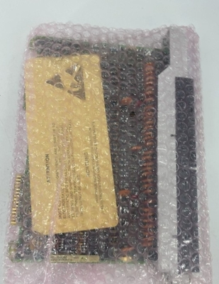
Packaging Details: | original |
Delivery Time: | 3-5 work days |
Payment Terms: | T/T |
Supply Ability: | 10 Piece per a day |
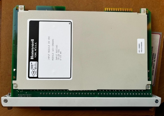
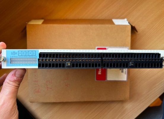
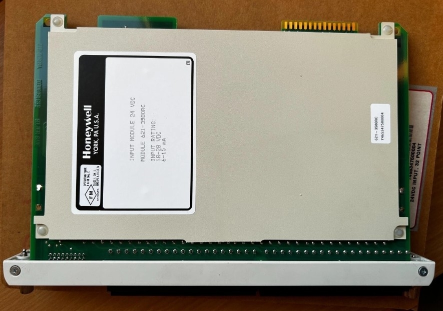
Product Name: | Honeywell 621-3580RC 24VDC 32 Point Digital Input Module For Industrial Automation | Product Model: | 621-3580RC |
---|---|---|---|
Condition: | New | Shipping: | DHL,TNT Or EMS,Fedex,UPS |
Stock: | Available | Warranty: | 12 Months |
Rating: | 24Vdc, 110mA | Packing Size: | 11.8" X 7.9" X 9.9" (30 Cm X 20 Cm X 25 Cm) |
Gross Weight: | 3kg |
Honeywell 621-3580RC 24VDC 32 Point Digital Input Module For Industrial Automation
Product Details:
Brand Name | Honeywell |
Model | 621-3580RC |
Catalog | TDC2000 |
Origin | United States (USA) |
Dimension | 30*25*20cm |
Weight | 3kg |
HS Code | 8537101190 |
Payment | T/T |
Sales Price | $800 |
Warranty | 12 months |
Lead time | 3-5 work days |
Additional Information:
CONFORMAL COATED 10 SLOT RACK | 7021_Experion Controller & I/O Hardware |
IOM TERM BLOCK 20POS | 7021_Experion Controller & I/O Hardware |
PWA- THERMOCOUPLE INPUT 6PT CIOM-A | 7021_Experion Controller & I/O Hardware |
AC INPUT 120VAC 16PT | 7021_Experion Controller & I/O Hardware |
7 SLOT RACK | 7021_Experion Controller & I/O Hardware |
Description:
Parallel I/0 configurations are designed for those applications in which long distances between 621 I/0 racks and the processor rack are not required. A maximum of 50 cable feet is allotted for parallel I/0 within a 620-06 system.
The l/0 Expander Module, is housed within the 620-06 rack and provides a 50-pin D connector. This connector is cabled to one of the two ports on a Parallel l/0 Module (PIOM) within the 621 I/0 rack. A maximum of two I/0 racks may be connected via the PIOM ports in a daisy-chain fashion. The 620-06 offers a maximum of 192 I/0 points in a 2K system.
The 620-06 processor module (620-0636) includes three 8-position DIP switches. One is located on the interface pcb; the other two are located on the Microprocessor unit (MPU) pcb.
SW1 on the interface board determines module response to fault conditions and other processor operations functions. SW 1 and SW2 on the MPU board identify the type of l/0 module (0-, 8-, 16-, or 32-point) to be in-talled in designated processor rack slots.
Contact Person: Candy Wang
Tel: +8618059279924