Place of Origin: | USA |
Brand Name: | Honeywell |
Certification: | COC |
Model Number: | 51401551-200 |
Minimum Order Quantity: | 1 Piece |
---|---|
Price: | inquiry |
Packaging Details: | original |
Delivery Time: | 3-5 work days |
Payment Terms: | T/T |
Supply Ability: | 10 Piece per a day |
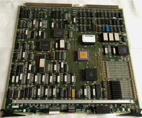
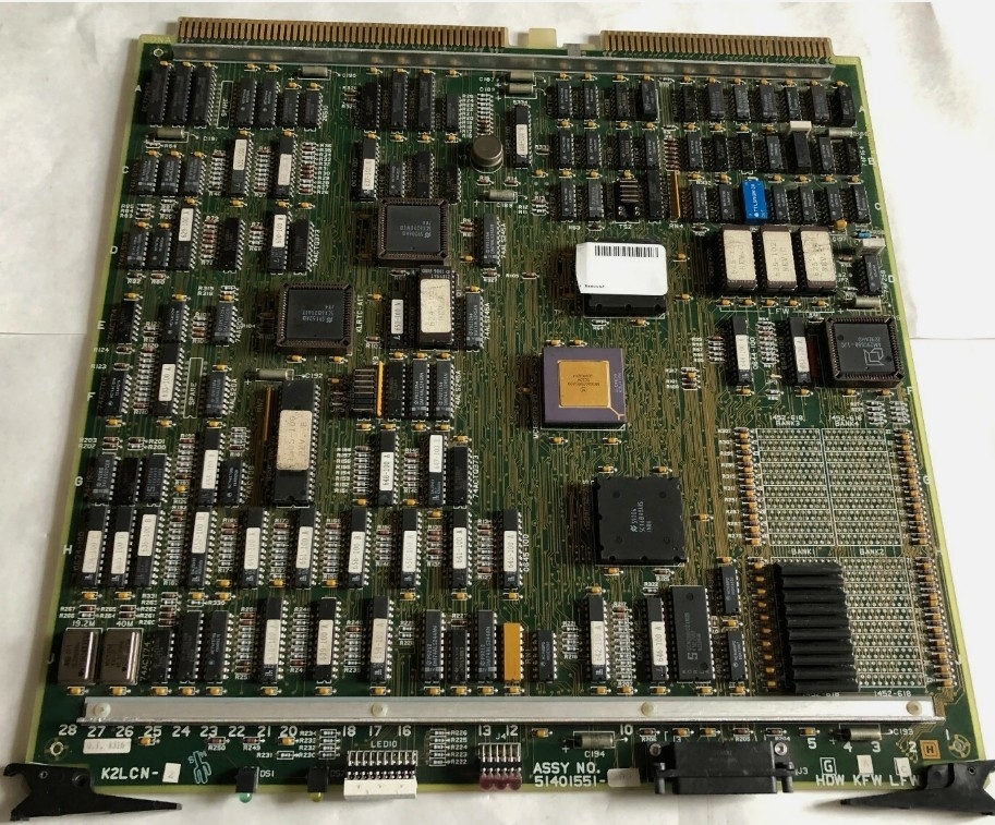
Product Name: | Honeywell 51401551-200 K2LCN-2 High Performance/Density Processor Board | Product Model: | 51401551-200 |
---|---|---|---|
Condition: | New | Shipping: | DHL,TNT Or EMS,Fedex,UPS |
Stock: | Available | Warranty: | 12 Months |
Rating: | 24Vdc, 110mA | Packing Size: | 11.8" X 7.9" X 9.9" (30 Cm X 20 Cm X 25 Cm) |
Gross Weight: | 3kg | ||
Highlight: | High Density Processor Board,Honeywell 51401551-200 Processor Board,High Performance Processor Board |
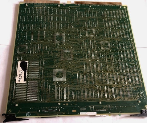
Honeywell 51401551-200 K2LCN-2 High Performance/Density Processor Board
Product Details:
Brand Name | Honeywell |
Model | 51401551-200 |
Catalog | FTA |
Origin | United States (USA) |
Dimension | 30*25*20cm |
Weight | 3kg |
HS Code | 8537101190 |
Payment | T/T |
Sales Price | $1200 |
Warranty | 12 months |
Lead time | 3-5 work days |
Additional Information:
K2LCN-2 | High Performance/Density Processor Board |
CNI I/O | Communications Network Interface I/O Brd (EC) |
CLI | Communications Line Interface Board |
TP485-4 | Temp.-Sensor I/O Face Plate w/o connector (EC) |
NIM MODEM | Network Interface Module MODEM Card |
Description:
The Multinode Module is designed to mount either horizontally in a standard NEMA rack or vertically in a cabinet (or tower) designed to stand vertically on the floor. Cooling is provided by four fans in one side of the module enclosure. An integral power supply is located at the bottom (or side) of the module.
Circuit board slots are numbered from 1 to 10 starting at the bottom (nearest the power supply). When the module is oriented vertically, the slots are numbered from right to left.
Nodes within a single Multinode Module are in a 3/3/2/2 arrangement, with slots 1 through 3 containing the first node, 4 through 6 containing the second node, slots 7 and 8 containing the third node, and slots 9 and 10 containing the fourth node.
The functional control boards are installed in the front card file of the module so that status indicators on the boards may be viewed through the transparent cover. If an Input/Output (I/O) adapter board (or paddleboard) is directly associated with a functional control board, it is installed in the slot behind it in a card file at the rear of the module. Paddleboards which do not perform an I/O function may also be installed in the rear card file in an unused slot.
Contact Person: Candy Wang
Tel: +8618059279924