| Place of Origin: | USA | 
| Brand Name: | GE | 
| Certification: | CO | 
| Model Number: | 531X305NTBAPG1 | 
| Minimum Order Quantity: | 1pc | 
|---|---|
| Price: | $1750 | 
| Packaging Details: | 6.4" x 6.4" x 4.8" (16cm x 16 cm x 12 cm) | 
| Delivery Time: | 5-8 work days | 
| Payment Terms: | T/T | 
| Supply Ability: | 10pcs | 
| Brand Name: | GE | Model: | 531X305NTBAPG1 | 
|---|---|---|---|
| Condition: | New | Gross Weight/Shipping Weight: | 2.2 Lbs / 35.2 Oz / 1kg | 
| Packing Size: | 6.4" X 6.4" X 4.8" (16cm X 16 Cm X 12 Cm) | Country Of Origin/Original Country: | United States (USA) | 
| Lead Time: | In Stock | Shipping Port: | Xiamen | 
| Payment: | T/T | Sales Price: | Inquiry | 
| Color: | Depends On Material | Warranty: | 12 Months | 
| Lead Time: | 5-8 Work Days | Courier Partners: | DHL, UPS, TNT, FedEx And EMS | 
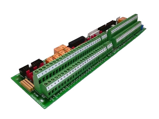
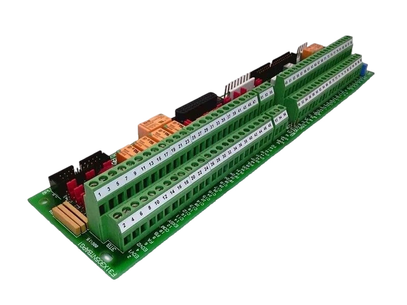
531X305NTBAPG1 GE TERMINAL DRIVE BOARD EX2000 Excitation System
Product Details:
| Brand Name | GE | 
| Model | 531X305NTBAPG1 | 
| Catalog | Mark VI | 
| Origin | United States (USA) | 
| Dimension | 16*16*12cm | 
| Weight | 1kg | 
| HS Code | 8537101190 | 
| Payment | T/T | 
| Sales Price | $1750 | 
| Warranty | 12 months | 
| Lead time | 3-5 work days | 
Additional Information:
| N/M | N/M | 
| GEH-6421 | Mark VI Turbine Control System Guide | 
| GEH-6403 | Control System Toolbox for Configuring a Mark VI Controller | 
| GEH-6408 | Control System Toolbox for Configuring the Trend Recorder | 
Description:
The 531X305NTBAPG1 GE is an NTB/3TB Terminal Board developed by GE under the EX2000 Excitation system. The drive (or exciter) cabinet houses the 531X305NTB (NTB/3TB) board. The drive's (or exciter's) connection terminals for the majority of external signal-level I/O are located on the board, along with passive interface circuitry. Plugs 6PL and 8PL from the drive control board, plugs 2PL and 4PL from the power supply board, plug COMPL from the terminal board 3TB, and plugs 2PL and 4PL from external equipment connect to the NTB/3TB.
Features a differential A-guad-B encoder interface with a marker channel for connection to the drive.
Optical lsolation: The encoder circuit is optically isolated on the drive control board.
Setup Flexibility: Jumpers enable configuration for +5 V or +15 V encoders.
Depending on whether positive or negative logic is employed, hardware jumpers are used to bias disconnected inputs to +24 or -24 V dc.
![]()
Contact Person: Candy Wang
Tel: +8618059279924