Place of Origin: | USA |
Brand Name: | GE |
Certification: | CO |
Model Number: | IS215VCMIH2BB |
Minimum Order Quantity: | 1pc |
---|---|
Price: | $3000 |
Packaging Details: | 6.4" x 6.4" x 4.8" (16cm x 16 cm x 12 cm) |
Delivery Time: | 5-8 work days |
Payment Terms: | T/T |
Supply Ability: | 10pcs |
Brand Name: | GE | Model: | IS215VCMIH2BB |
---|---|---|---|
Condition: | New | Gross Weight/Shipping Weight: | 2.2 Lbs / 35.2 Oz / 1kg |
Packing Size: | 6.4" X 6.4" X 4.8" (16cm X 16 Cm X 12 Cm) | Country Of Origin/Original Country: | United States (USA) |
Lead Time: | In Stock | Shipping Port: | Xiamen |
Payment: | T/T | Sales Price: | Inquiry |
Color: | Depends On Material | Warranty: | 12 Months |
Lead Time: | 5-8 Work Days | Courier Partners: | DHL, UPS, TNT, FedEx And EMS |
Highlight: | Mark VI Custom Industrial Circuit Board,GE IS215VCMIH2BB Circuit Board |
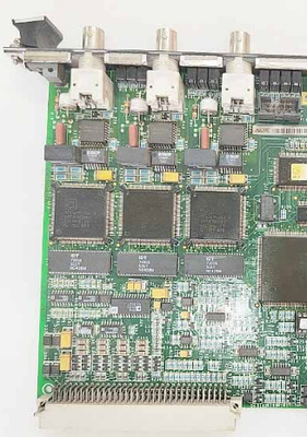
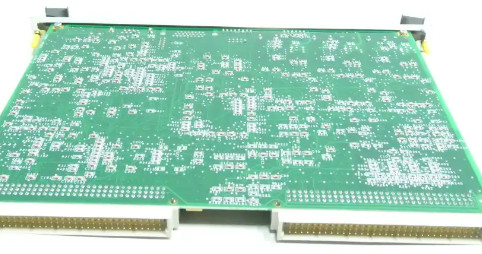
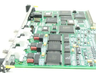
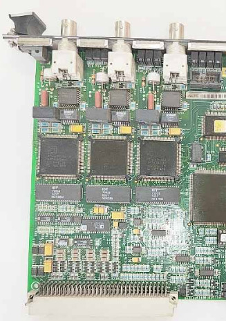
GE IS215VCMIH2BB Circuit Board Mark VI Custom Industrial
Product Details:
Brand Name | GE |
Model | IS215VCMIH2BB |
Condition | New |
Gross Weight/Shipping Weight | 2.2 lbs / 35.2 oz / 1kg |
Packing Size | 6.4" x 6.4" x 4.8" (16cm x 16 cm x 12 cm) |
Country of Origin/Original Country | United States (USA) |
Lead Time | In Stock |
Shipping Port | Xiamen |
Payment | T/T |
Sales Price | Inquiry |
Color | Depend on product |
Warranty | 12 months |
Lead time | 5-8 work days |
Courier partners | DHL, UPS, TNT, FedEx and EMS |
Additional Information:
N/M | N/M |
Description:
The IS215VCMIH2BB module typically offers multiple voltage and current input channels, allowing it to receive signals from a wide range of sources, such as sensors, transmitters, or other devices. It can measure both AC and DC voltage and current.
The module may feature built-in signal conditioning capabilities to ensure accurate measurement and monitoring of the voltage and current signals. This can include amplification, filtering, or isolation of the input signals.
The module is typically designed for easy installation and integration into standard racks or cabinets. It may feature connectors or terminals for efficient wiring and connection with other devices.
The alarm system collects and time stamps the diagnostic alarm messages at frame rate in the control module and displays the alarms on the HMI. Communication links to a plant DCS can contain both the software (system) diagnostics and composite hardware diagnostics with varying degrees of capability depending on the protocol’s ability to transmit the local time tags. Separate manual reset commands are required for hardware and system (software) diagnostic alarms assuming that the alarms were originally designated as latching alarms, and no alarms will reset if the original cause of the alarm is still present.
Each circuit board and terminal board in the system contains a serial number, board type, and hardware revision that can be displayed. Thirty seven pin D type connector cables are used to interface between the boards and the J3 and J4 connectors on the bottom of the control module. Each connector comes with latching fasteners and a unique label identifying the correct terminal point. One wire in each connector is dedicated to transmitting an identification message with a bar-code serial number, board type, hardware revision, and a connection location to the corresponding I/O board in the control module.
Contact Person: Candy Wang
Tel: +8618059279924